This week we learned about Computer-Controlled Machining, creating toolpaths and operating CNC router machine, and testing runout.
Requirements
- Complete your lab's safety training.
- Test runout, alignment, fixturing, speeds, feeds, materials and toolpaths for your machine.
- Document your work to the group work page and reflect on your individual page what you learned.
Group Assignment
Individual Assignment
- Make (design+mill+assemble) something big.
Softwares 💻
- Fusion 360
- ArtCAM
- Mach3
- openBuilds Control
Group Assignment
In this week we're operating the CNC router Machine and making something big! like any manufacturing technique we have to run some tests to make our design ready for the machine.
Safety
We got over the basics which are:
- Never leave the room while the machine is routing.
- Don't put any part of your body near to the cutting tool when it is moving.
- Always use eye, hearing protection and a mask When the machine is working.
- Make sure that all workpieces are securely clamped down.
- Always make sure you have inserted the correct bit for the job you are doing.
- If the bit is acting up or breaks, shut down the machine straight away.
Tests
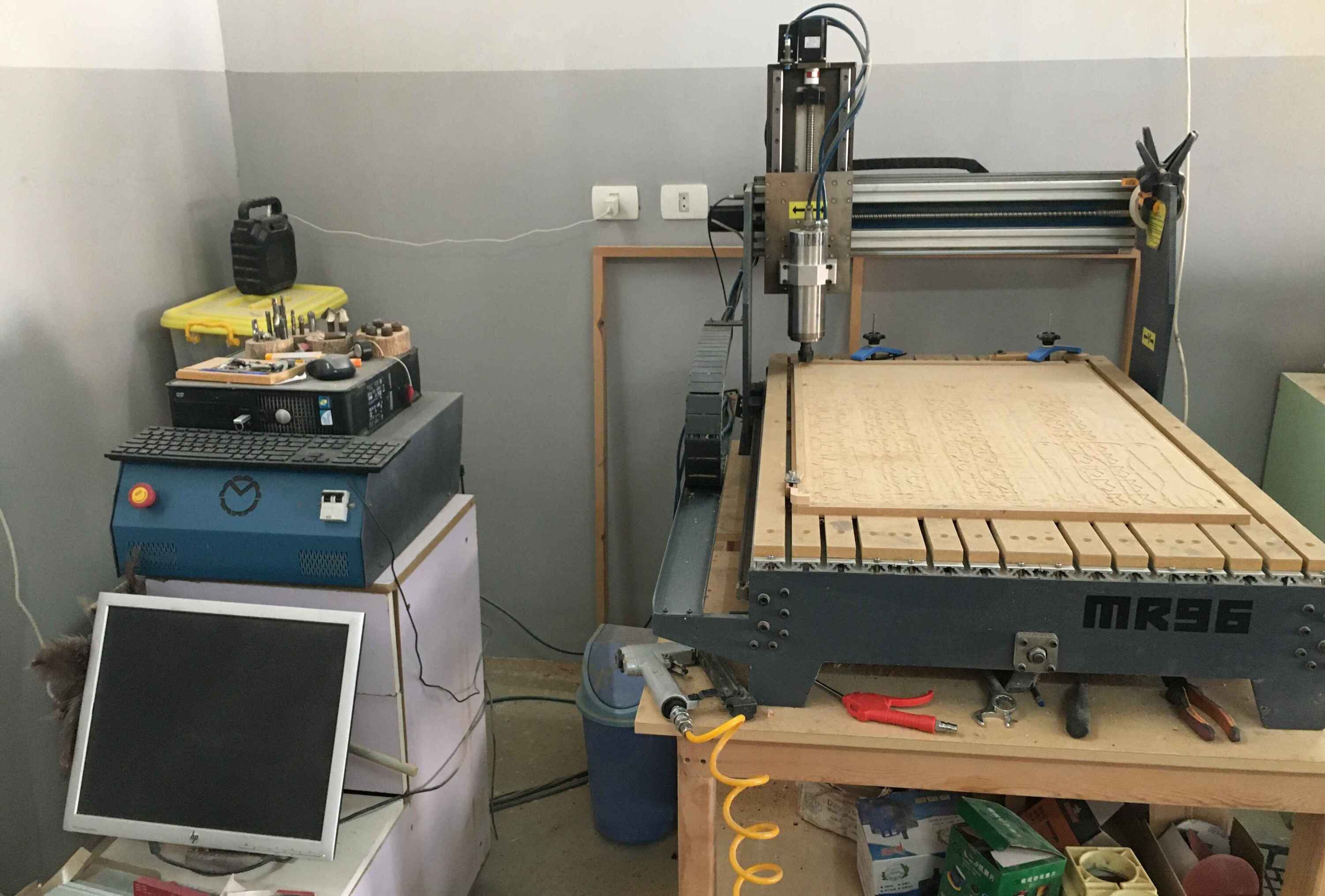
We don't have a CNC Router in our lab but we have a small CNC Milling machine that has a 30*40 working area and, so we made the tests on it first and since it's the same concept we'll make the same test on the CNC Router when we have access to it. We went through the different types of endmills and which is used for which job.
Our Machine
The Other Machine
This week we accessed the CNC router on of our community has. His name is Ahmed Hussien and he own the brand called . "Wonder Box". Big Thanks to him. He has a CNC Router machine made by an Egyptian company called "ElMalky". It has dimentisons of 60*90 cm.
Runout
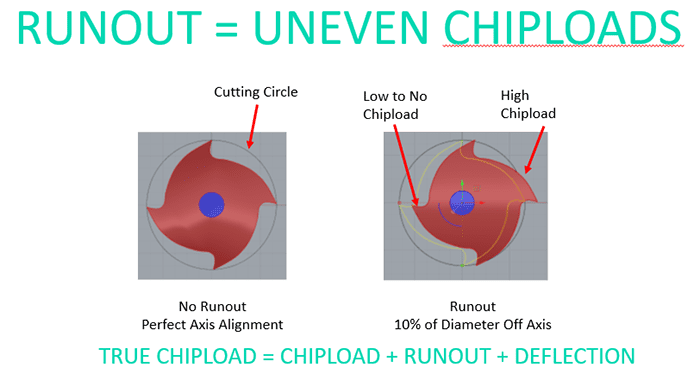
Runout is the inaccuracies that cause a tool to spin off the ideal axis. It typically uses dial test indicators to be measured. We didn't have it at our lab so we calculated the runout manually using multiple pieces. We measured the length from the workpiece minus the output piece and divided by two.
on China Router
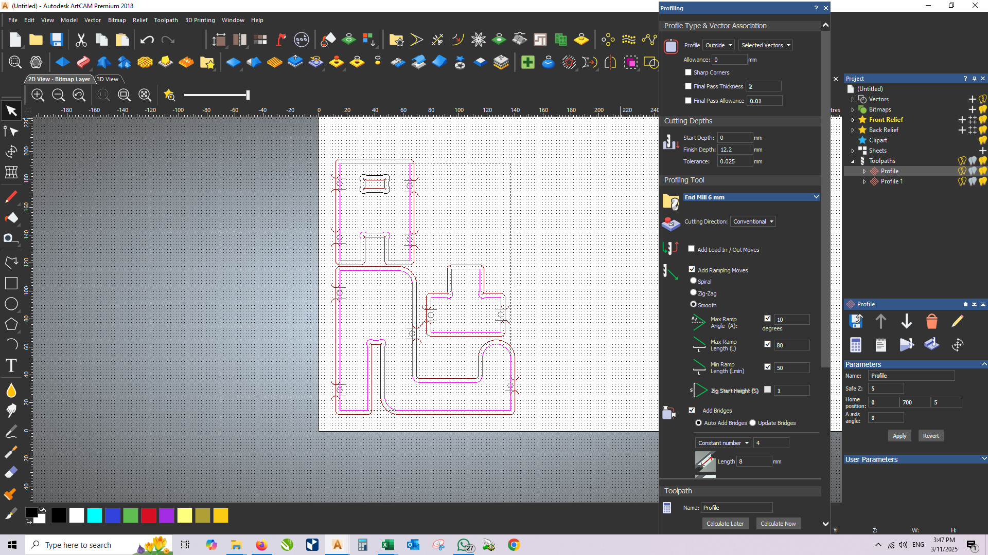
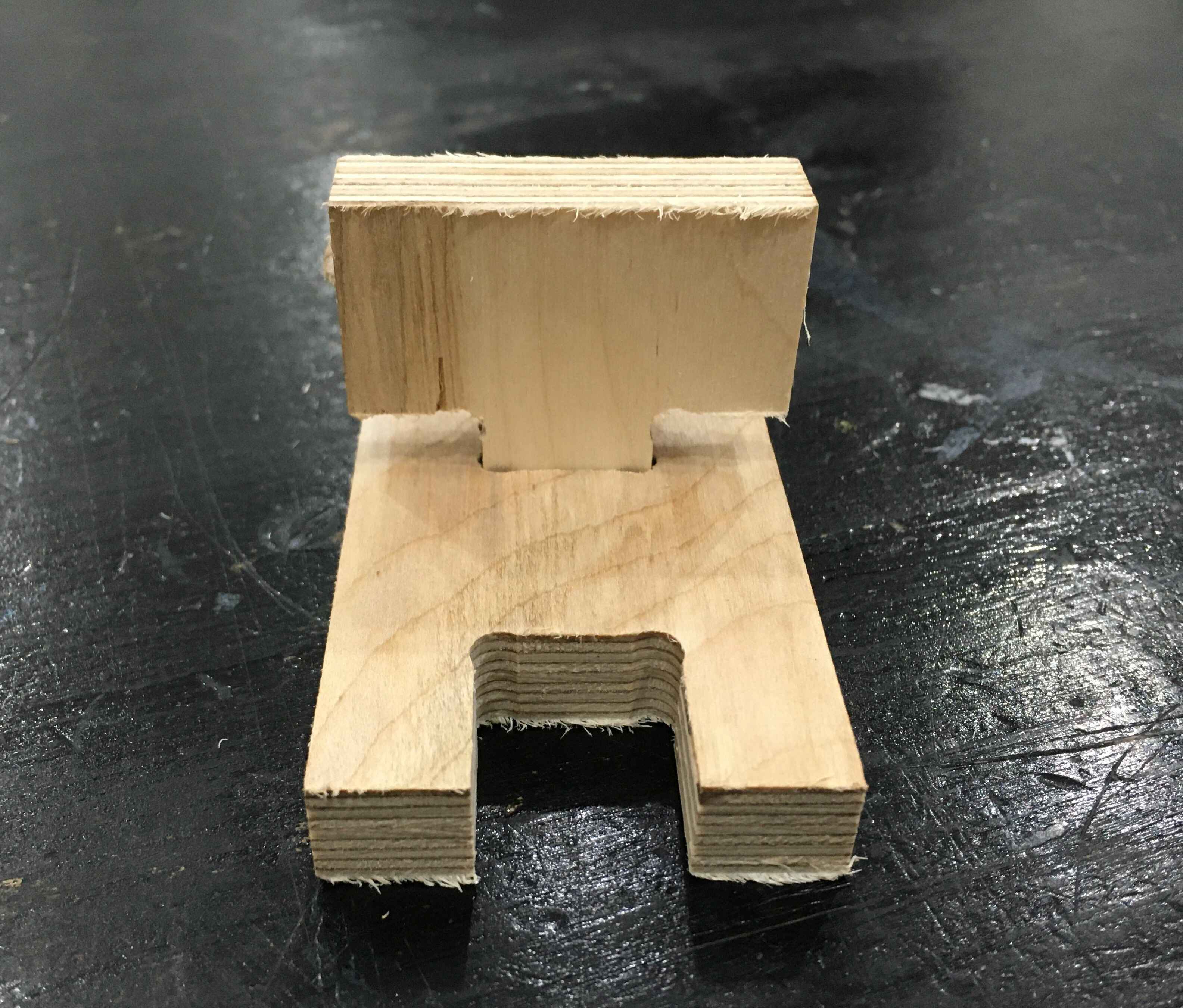
We used artcam to make the CAM Toolpaths.I'm going to talk about some interesting concepts to me later.Once we calculated the runout which was between 0.04 to 0.1, we made the second test part
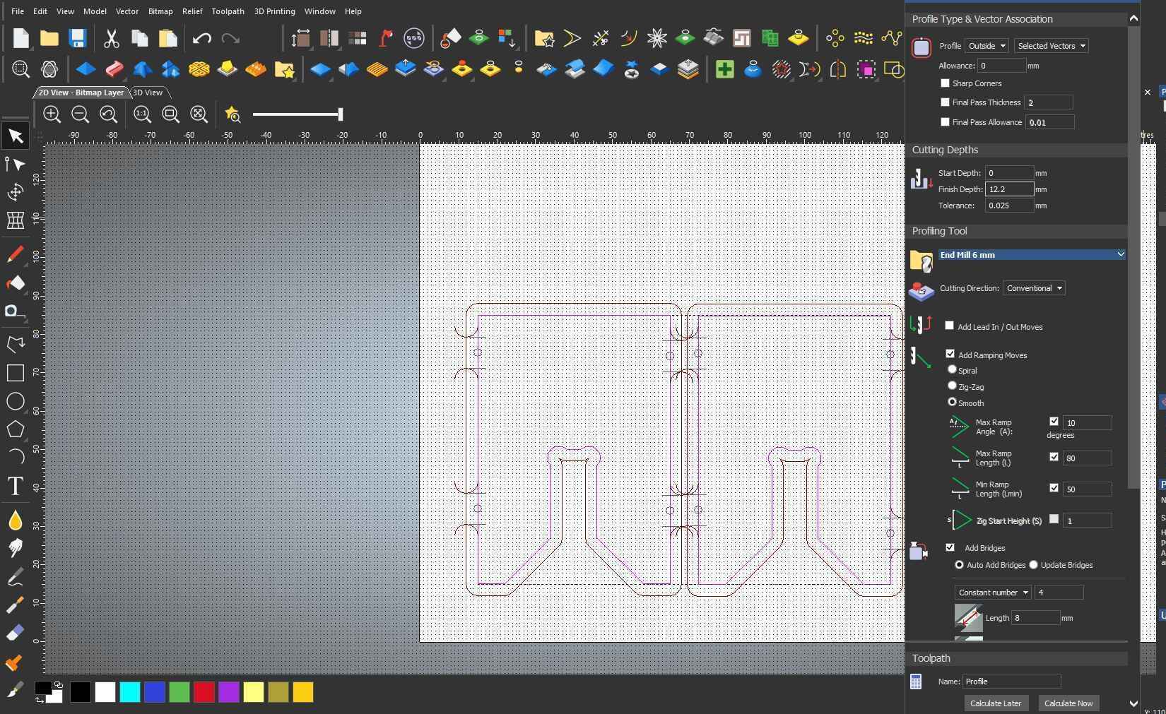
Second test part
On El Malky Machine
Sidetable
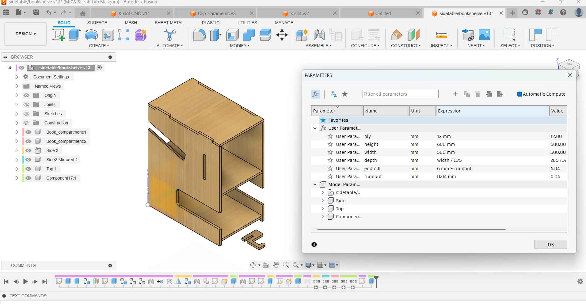
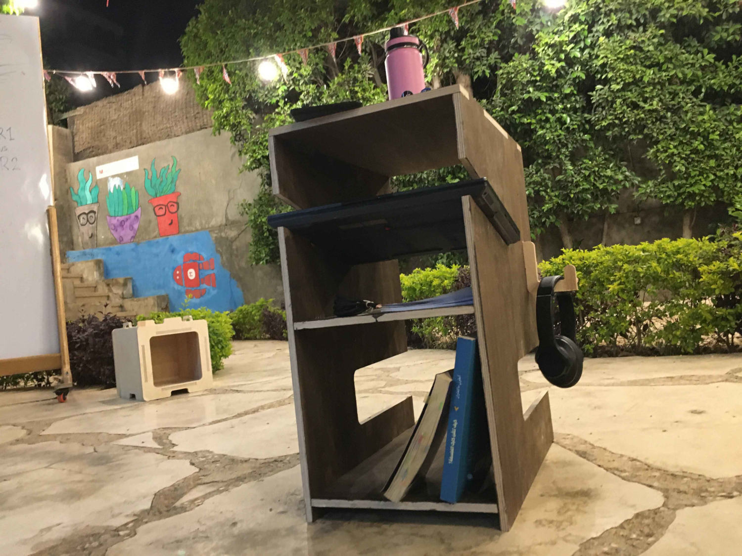
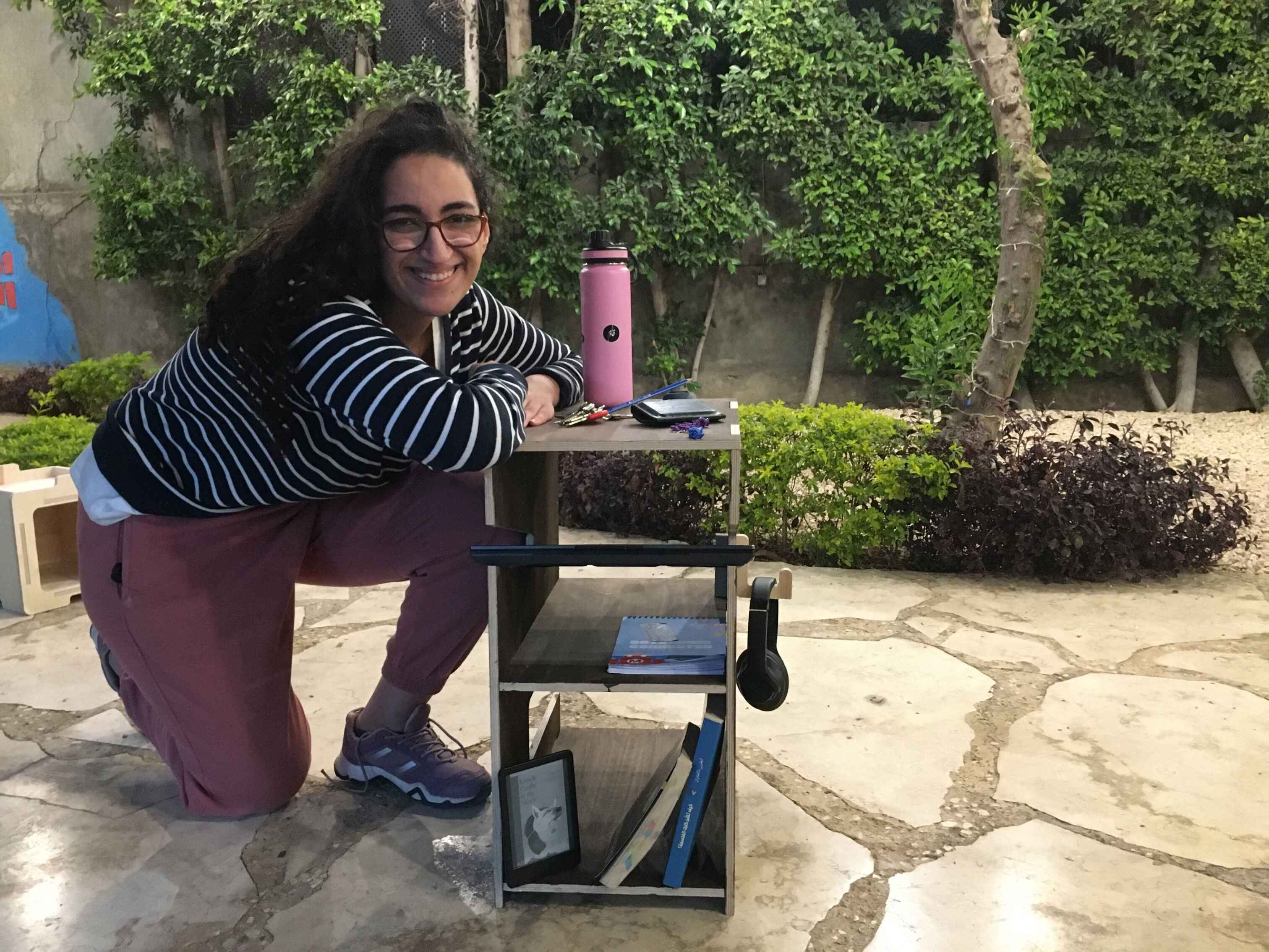
I'm not originally from Cairo but I'm a small-town girlie. I moved in here last year and I still have minimum amount of furniture and I'm an avid reader so my books are scattered all over the place. I wanted to make a piece that can both hold my laptop, headphone and books. I browesed Pintrest until I found this minimal design. It's a side table with plenty of room for everything. I made the design in Fusion 360. I used these parameters. I started to design the sides then the shelves compartments and finally the top.
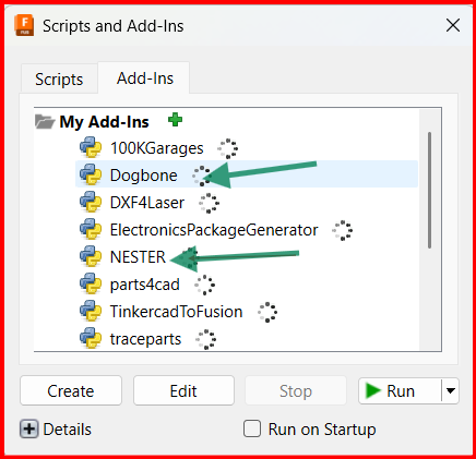
To design something to be CNC, you have to put dogbones. This is a helpful video on why but basically we're cutting with a spinning round tool so sharp corners will never be sharp and result in problems while assembly, So we add dogbones. You can either draw them or use a plugin like I did. It's called.. yep like you guessed:"Dogbones". I also added a plugin called NESTER to help nest the parts automatically but It didn't work.
Process.
- I started after adding all my needed parameters, I started sletching the side.
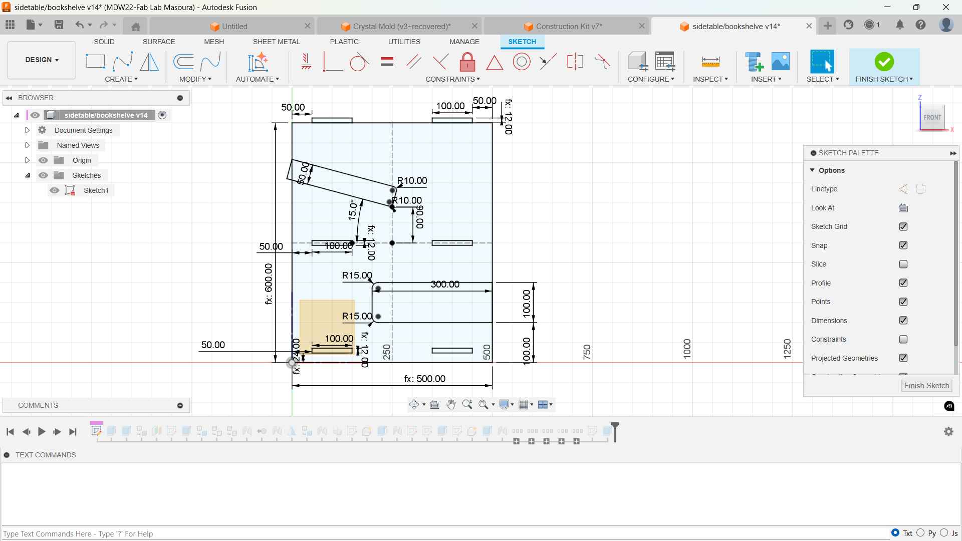
Sketching the side
- I extruded the side to the side then extrude cut the joints with only half the wood thickness.Then I created a mirrored side via the mirror tool to create the second side.
- I went ahead and sketched the shelves & extruded them.
- I sketched the top on w7_sides' joints and projected them. To constrain the part I used the coincident tool on the top's with the side's length.
- Then I decided to add the headphone holder and I used the hooked sloting joint I saw in this video Then sketched the part.
- Feedrate "2000" for plywood
- spindle RPM of"1500"
- Added ramping movement which will help elongate the endmil's life and make the machine not plunge 90deg in the plywood.
- Design Files DXF
- Sidetable f3D Files
- Design Files SVG
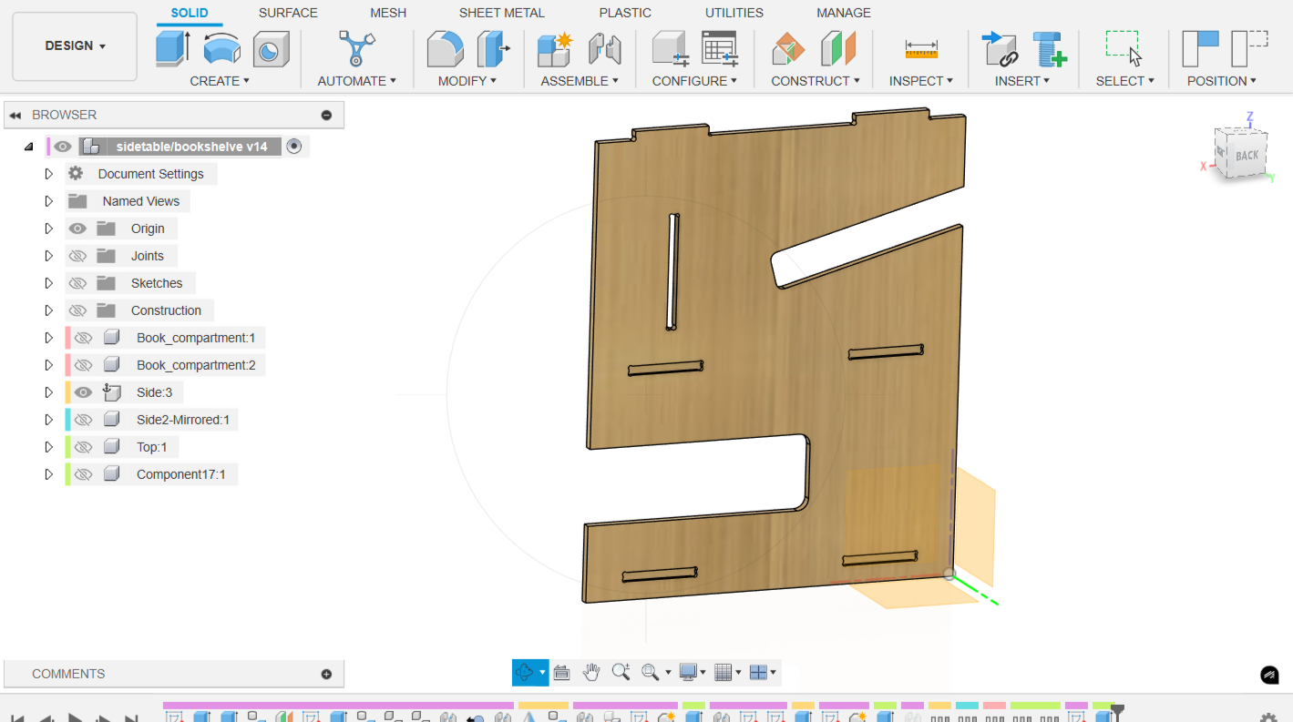
Extrude
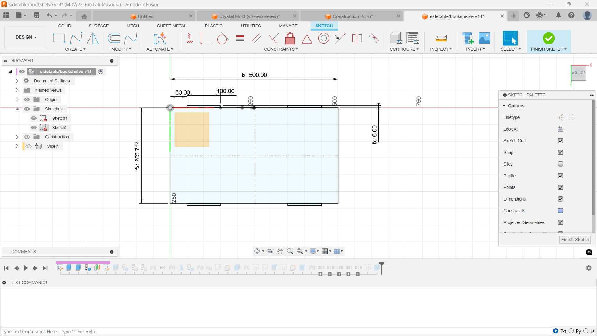
Shelf sketch
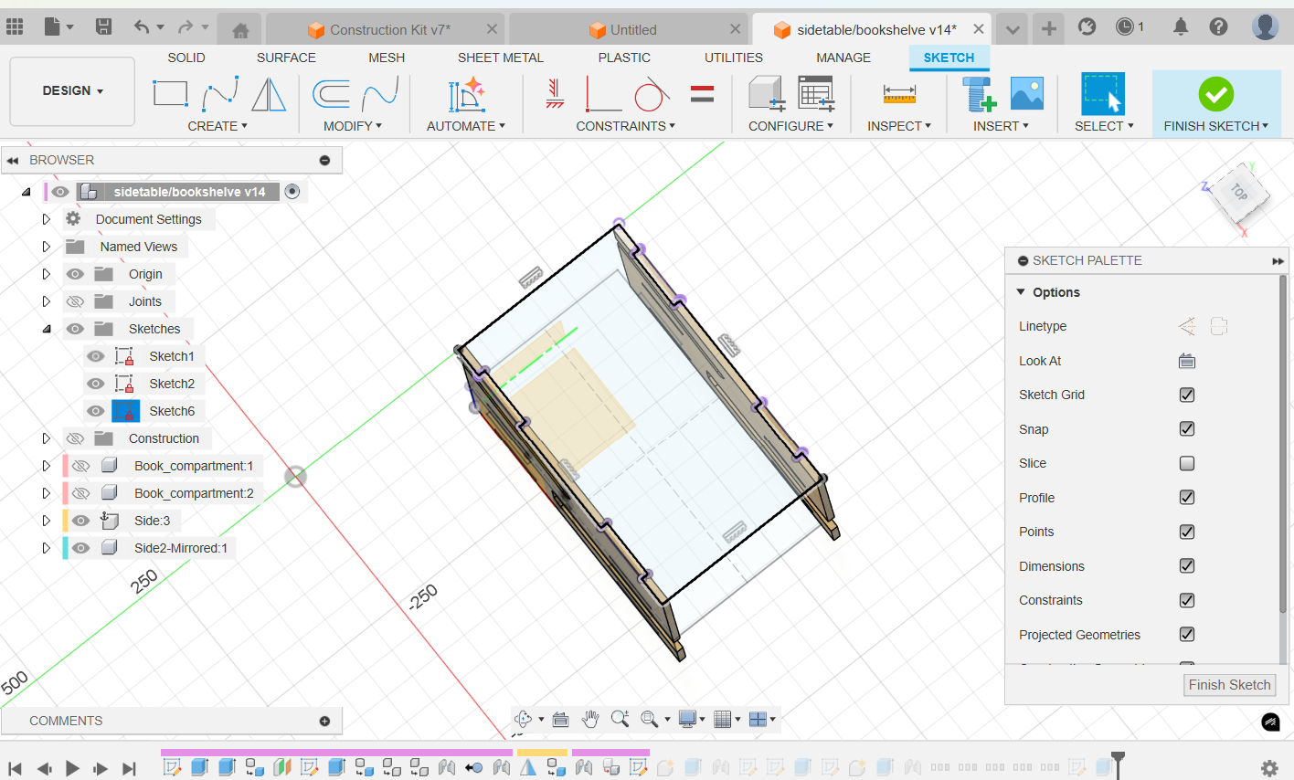
Top sketch
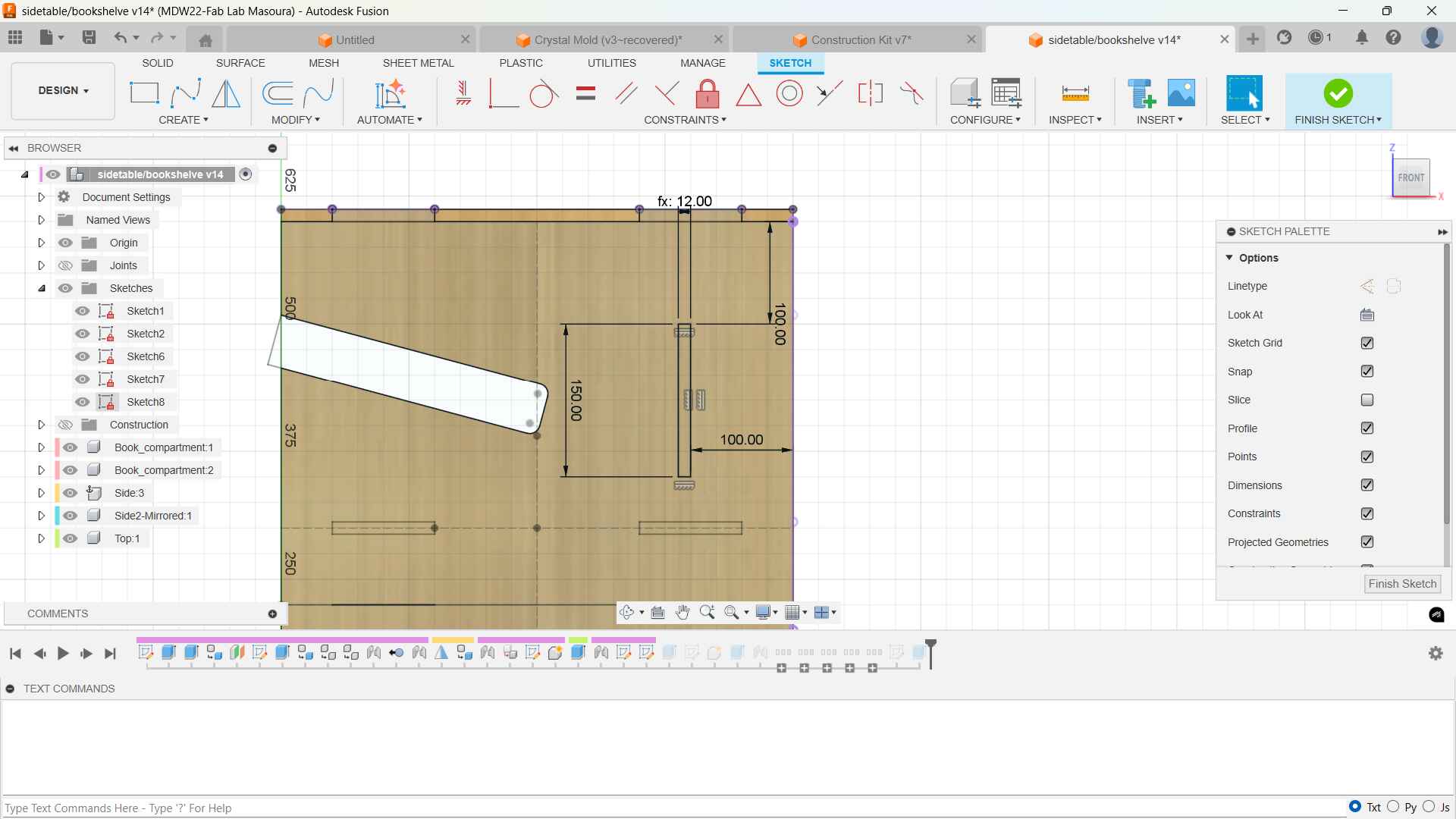
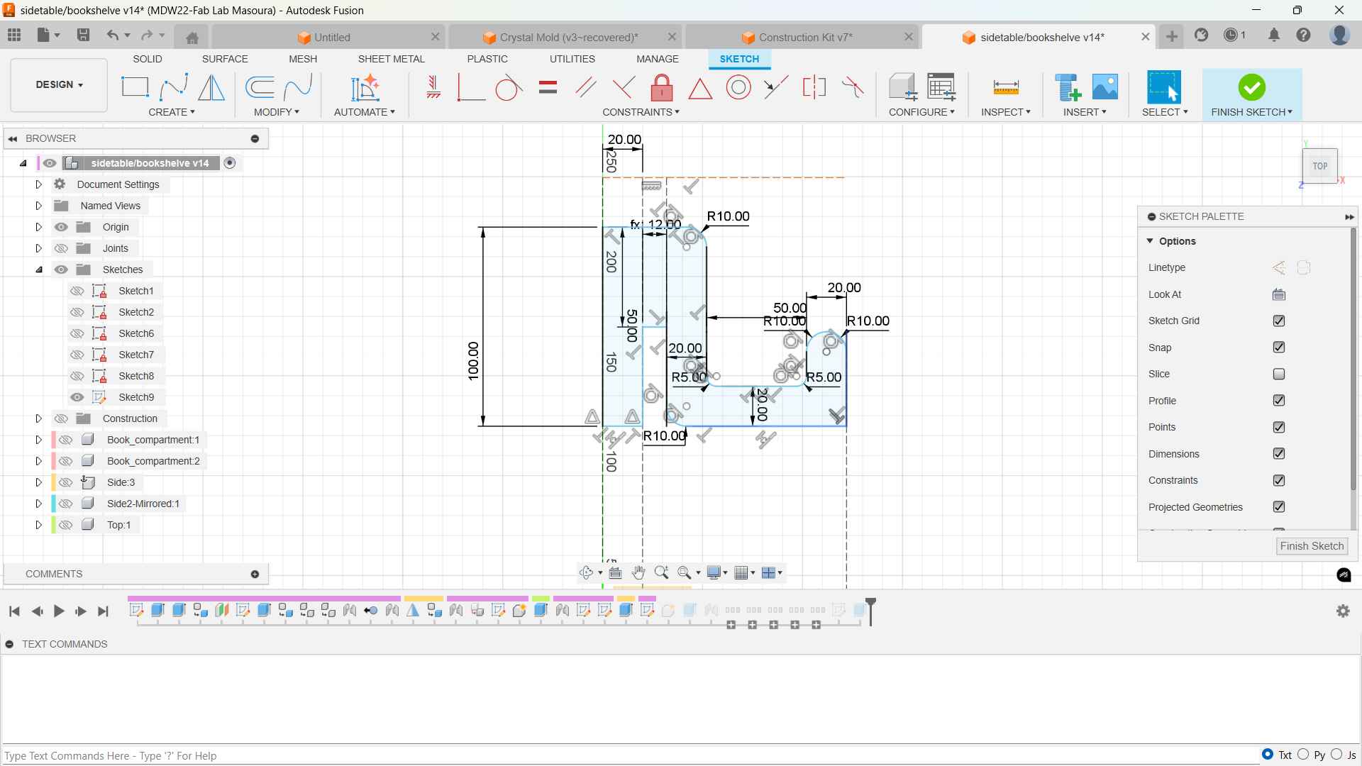
hook sketch
Mock-up with the Laser Cutter
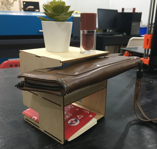
To test everything, I made a mock-up with the laser cutter by scaling the design to quarter of its size. I used 3mm plywood and it was a success. For using the laser machine please refer to this week.
Preparing Toolpaths
To start here we'll be using 6mm bit and 12mm plywood. We continud using artcam and Ahmed recommended using some parameters that will both make our design look good and make the machine work smoothly. One of the things that's really important is the plywood's fiber direction how each piece will hold itself against the other, this will help in making the part strong when assembled.
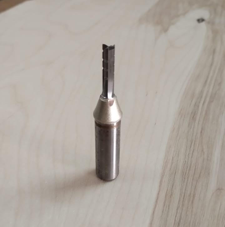
6mm bit
Parameters
.jpg)
And bridges which help secure the pieces to the bigger sheet to avoid any accidents of the piece detaching, we used the 3D bridges and readjusted their position to be in the top and bottom to each side of the piece. Also, we chose conventional over climb cutting.
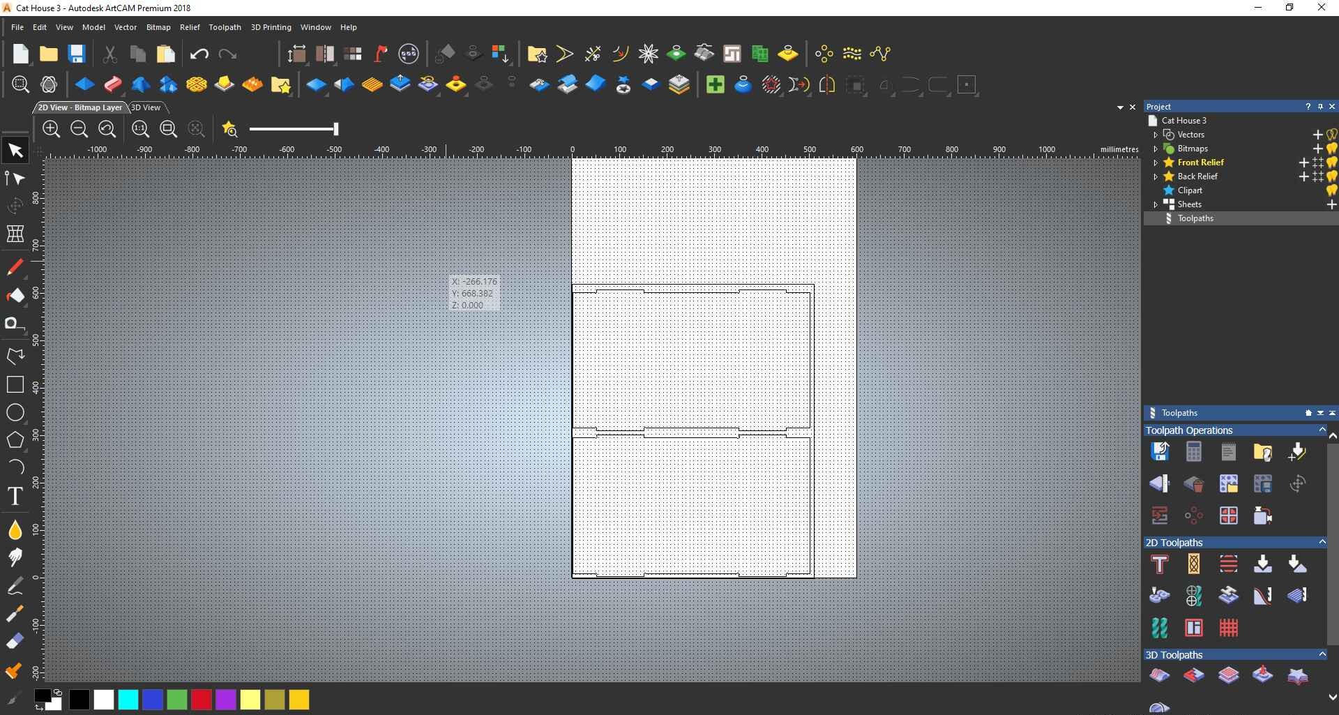
Adding the design
.jpg)
Choosing our endmill
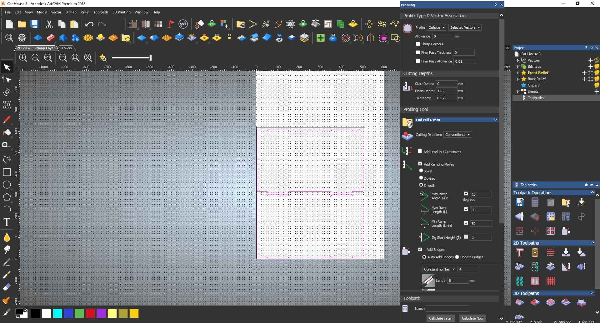
Toolpath parameters
.jpg)
Toolpath parameters
These parameters were applied for each design file. Then I exported the each file in G-code format that was suitabe for the machine. the extension was "tap". I copied the files to a USB Drive and went to the PC that was connected to the Machine. It already had Mach3.
Operating the Machine
First I load the G-Code made by ArtCAM From USB drive. Then I nailed the wood pieces and moved the spindle to origin point by clicking "Go To Zero" button. After homing I clicked on Cycle Start (The green button) to start routing.
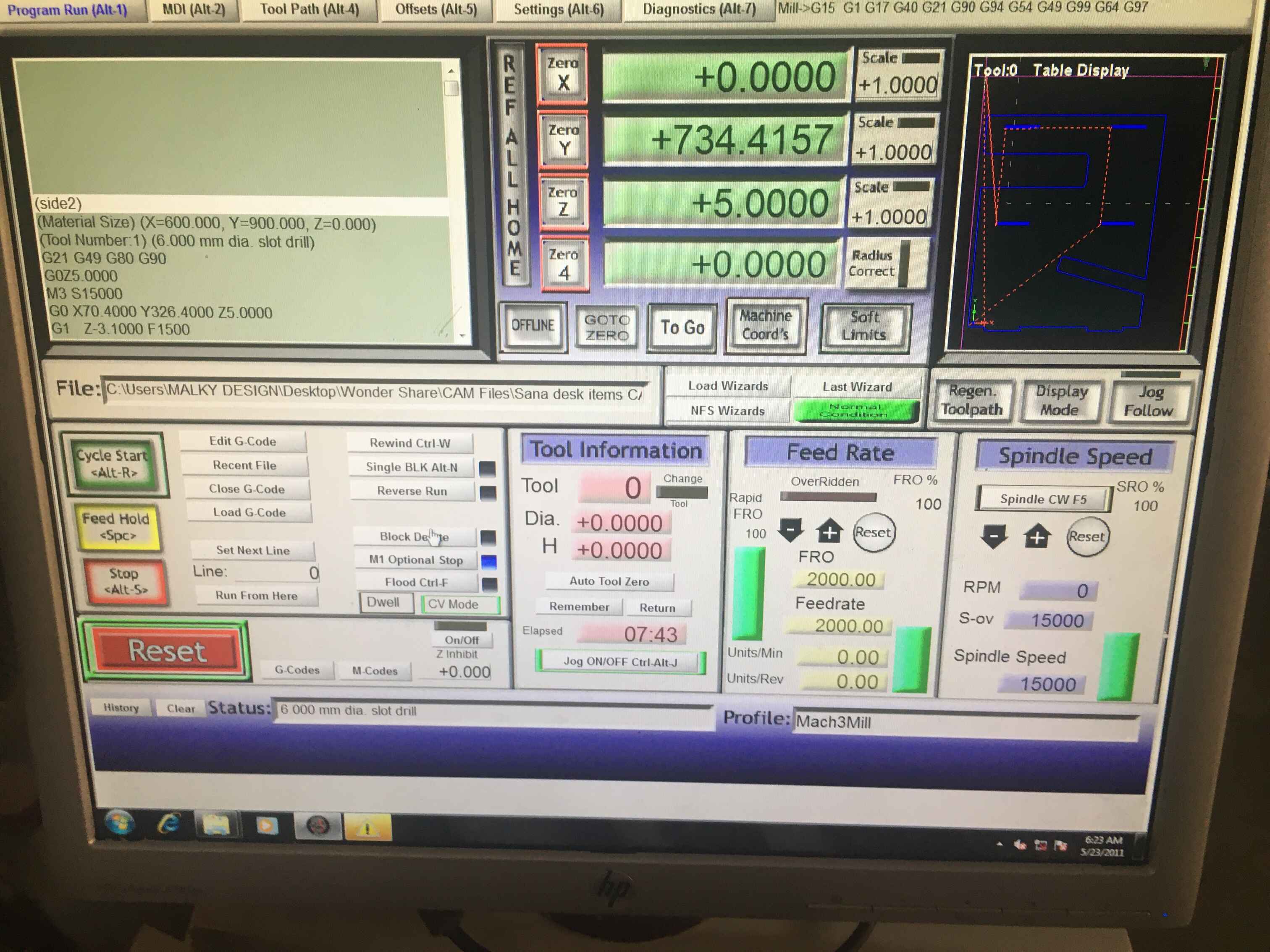
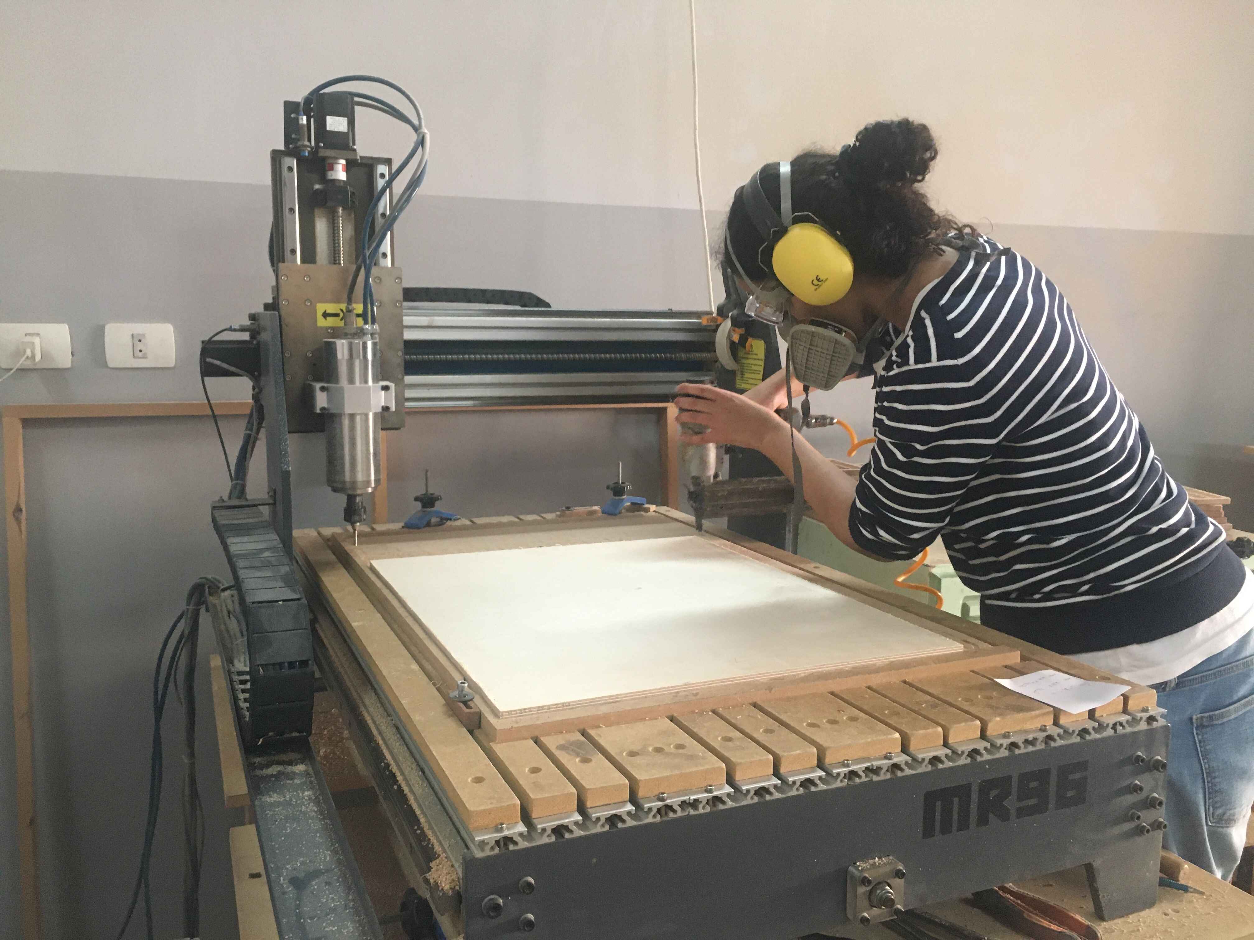
Here I used the nail gun to secure the wood.
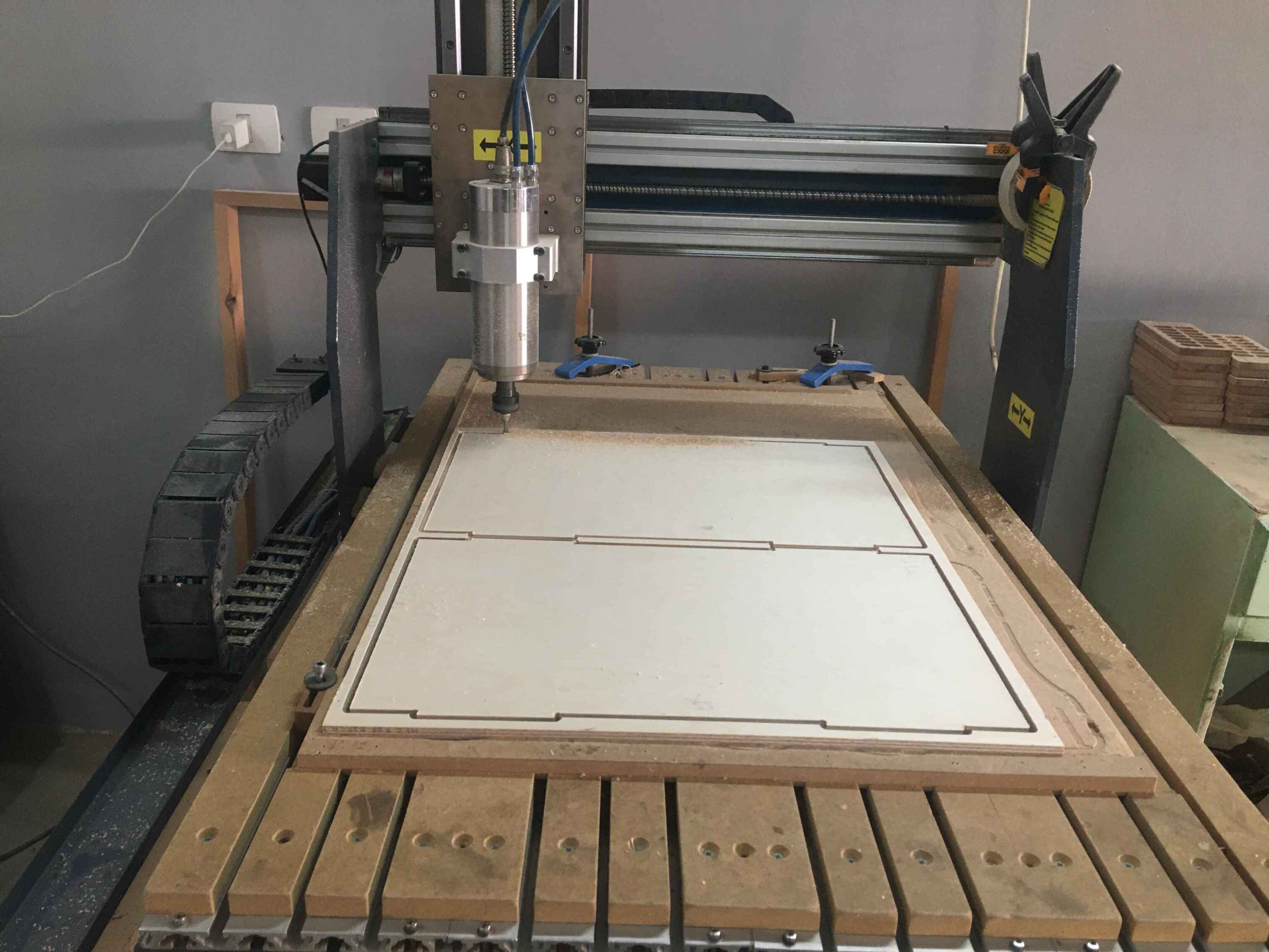
I didn't face any challenges except at securing the wood phase, I would hit the nail way to close to the origin and then resecured it again but hit the nail a bit farther to make sure it doesn't hit the endmill while working.
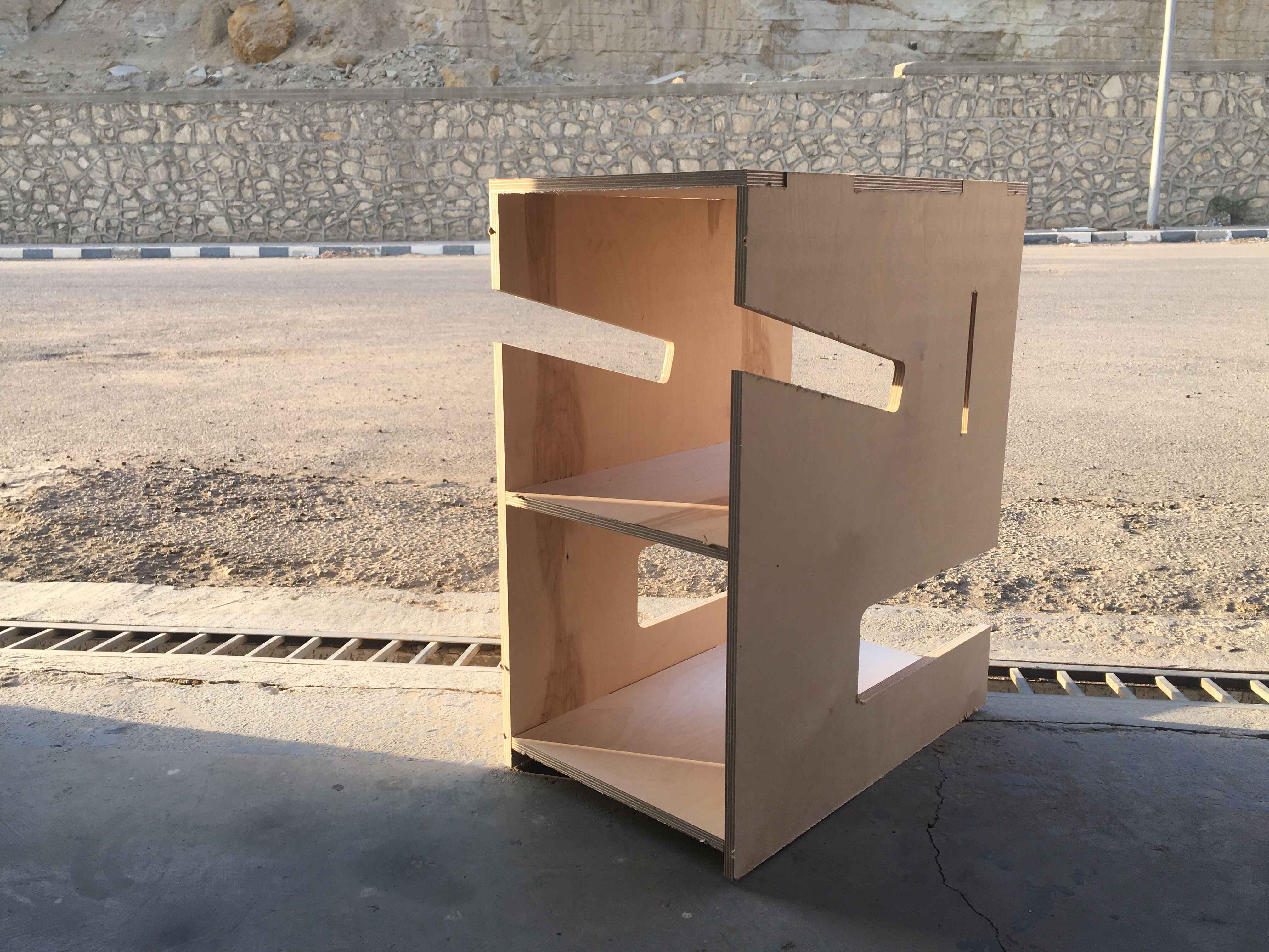
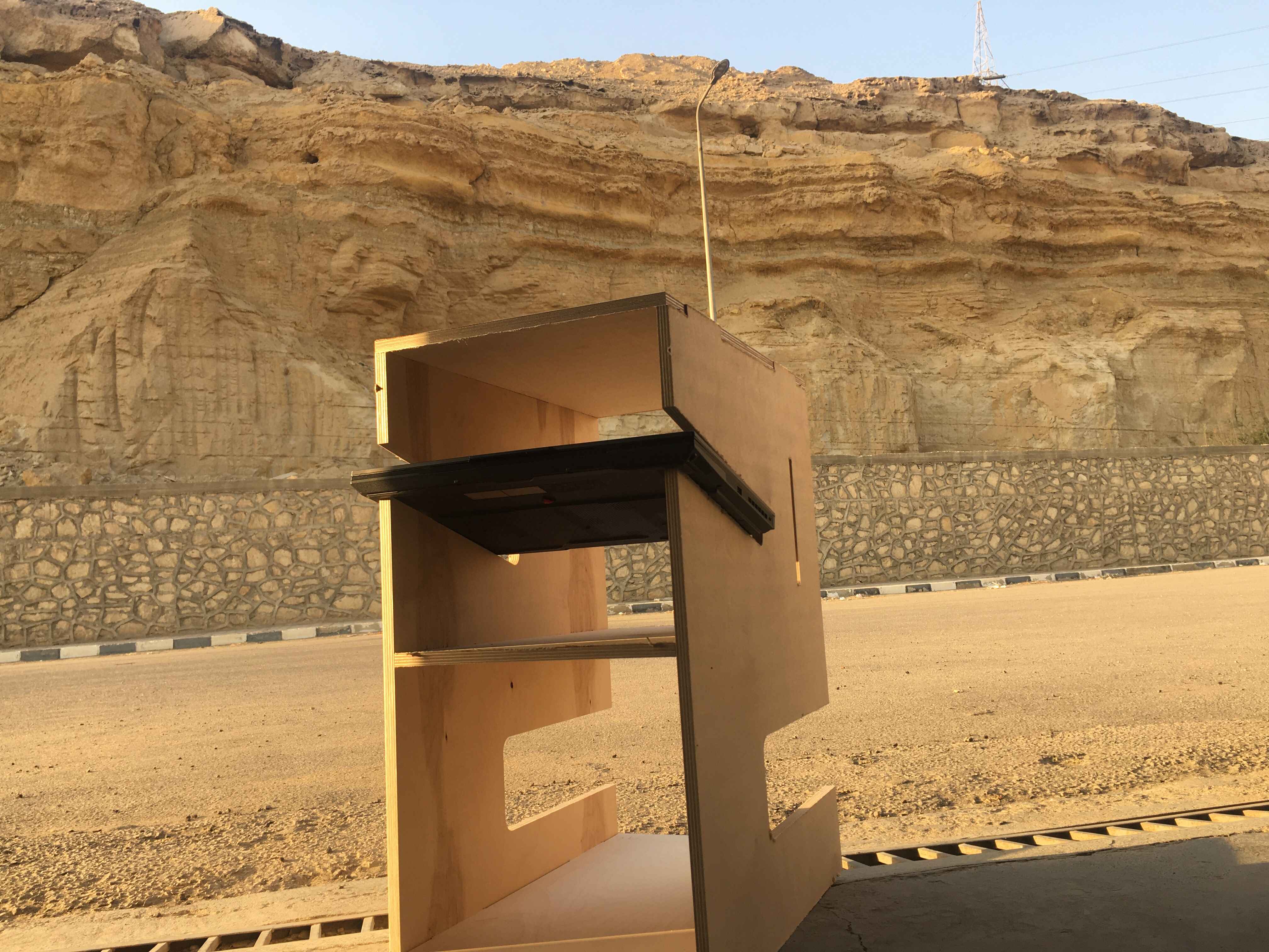
Multiple Hero Shoots!
Post-processing
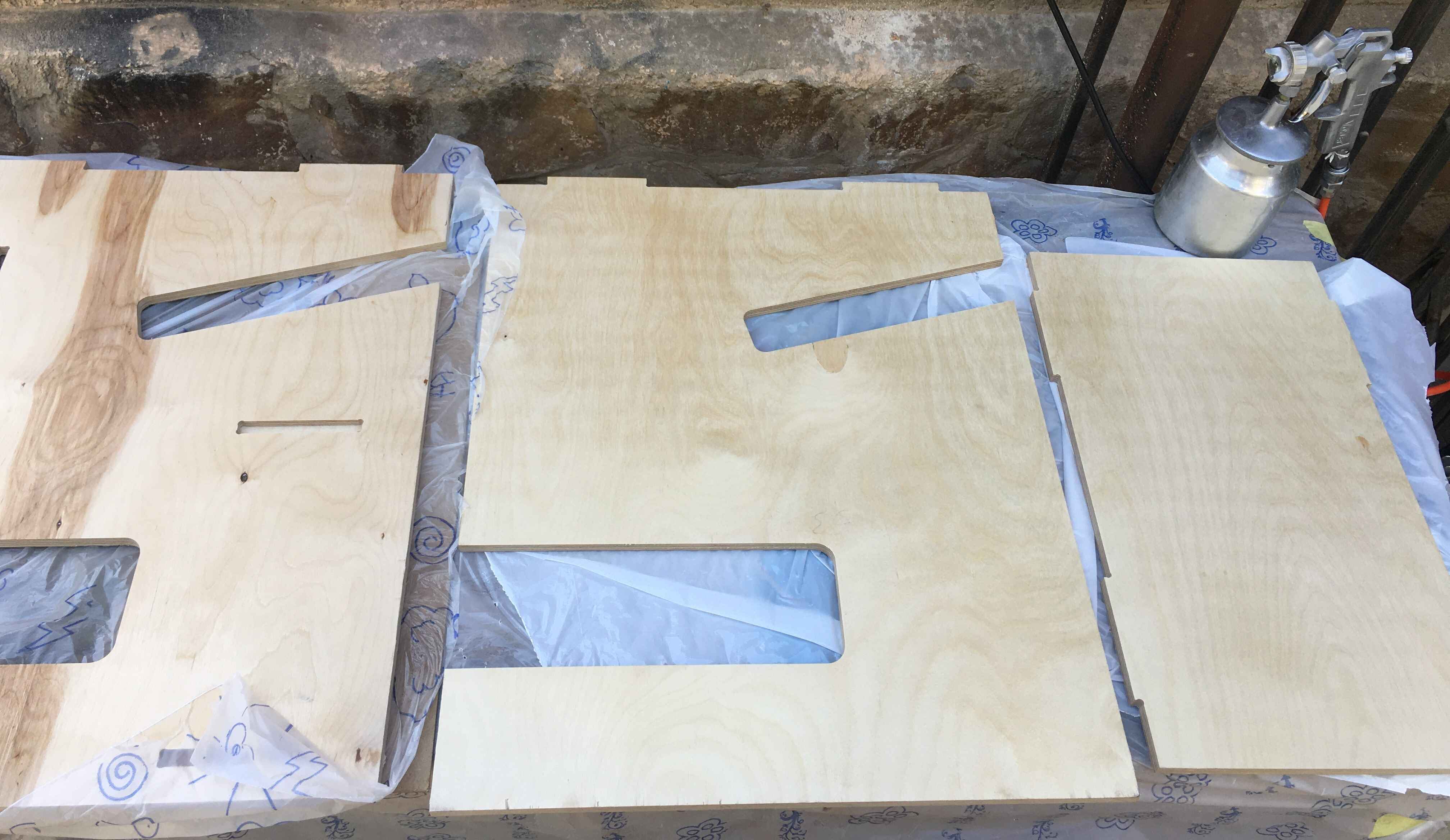
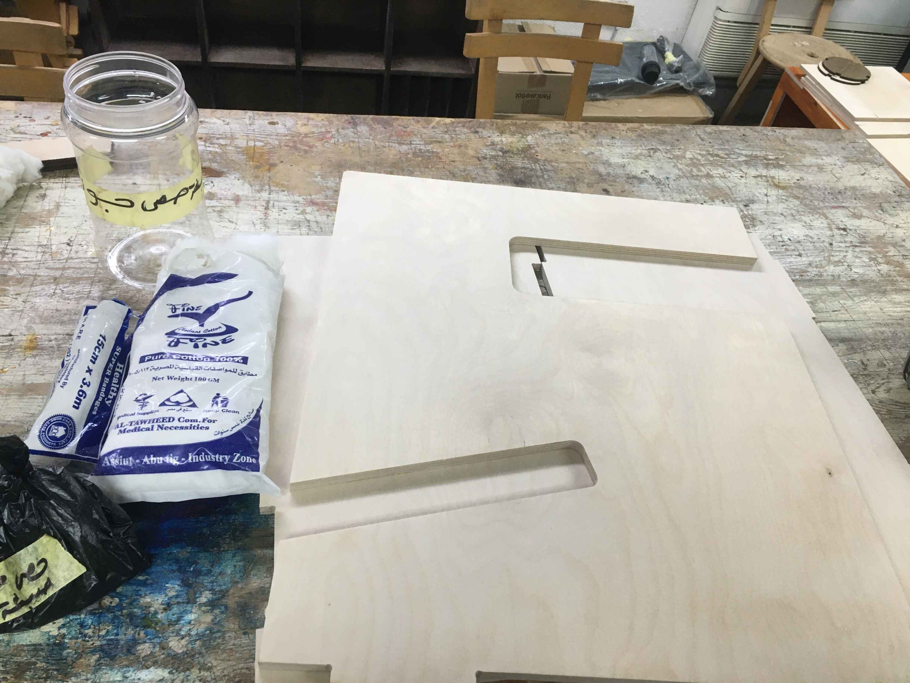
I used the sander to sand the pieces for-what-felt-and-actually-was HOURS. removed all the unnesseracy bits caused by the bridges.
Then it was time for sealer and sanding and finally staining I used a water-based wood stain made from natural Chestnut.
